Setting up the beamline
In this section, we will discuss methods to prepare the beamline prior to data collection. We will assume the reader has some familiarity with the instrument itself and basic operating procedures will not be provided.
The general strategy for this measurement will be to utilize the high dynamic range of the CCD image detector to measure the specular reflectivity with up to 7 orders of magnitude dynamic range. This is achieved by attenuating the incoming beam with various upstream optics at low incident angles (to prevent saturation and damage) and increasing flux at higher angles to offset the low intensity reflections.
Prior to arriving at the beamline
Make sure the beamline scientist is aware of your intention to run p-RSoXR.
- Setup the Piezo Shutter
The Piezo shutter allows for shorter dwell times (down to 1 ms) enabling direct images of the beam.
A cable hookup enables a bypass to the pneumatic shutter and allows the piezo to recieve signals from the software.
For new users, this should be done by the staff scientist
- Budget your beamtime
P-RSoXR is not a fast measurement.
- We recommend budgeting 20 minutes per scan for sample thicknesses 70-100nm.
Thinner samples require less time than thicker samples.
Each sample will also require approximately 20 minutes for alignment.
Mounting samples
Several samples plates are available at the beamline suitable for reflectivity. Samples are typically taped to a plate using double-sided sticky carbon tape. This ensures the sample will not move during theta-scans while providing sufficient conductivity if the user would like to measure TEY NEXAFS.
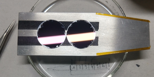
Sample plate ready for measurements.
Samples should be at least 1cm x 1cm to allow enough real-estate to move the beam between different measurement conditions. This helps limit exposure on a single spot and reduces beam damage.
Note
Be sure to include a piece of YAG (to locate the beamspot) and something to calibrate the energy (polystyrene or HOPG will work). Both can be provided by the beamline scientist.
Reflectivity holders are not often utilized and will likely not have any references attached by default.
Instrument setup
Once samples have been loaded and the base chamber pressure has been achieved, we can begin to setup the instrument for reflectivity.
- These steps can be carried out while the camera is being cooled down to -45 C
- Move the photodiode into the field of view.
Use the trajectory screen to move to the Photodiode Far position
Verify the beam spot using the YAG crystal.
- Align JJ slits if not done so by beamline scientist
- Default reflectivity settings for vertical and horizontal aperture size:
Upstream JJ Apertures = 0.1[mm]Middle JJ Apertures = 0.4[mm]In-Chamber JJ Apertures = 0.8[mm]
Changing the
Upstream JJ Aperturesis an option to increase/reduce flux if you need more options.
- Measure the intensity of the direct beam (with the photodiode)
Either measure a reference energy or run a short scan over the elemental edge of interest.
Periodically check the direct beam using the photodiode. Changes in intensity may require adjusting dwell times later on in the run.
- Calibrate the photon energy using a reference sample.
An energy offset can be applied during the runfile if necessary.
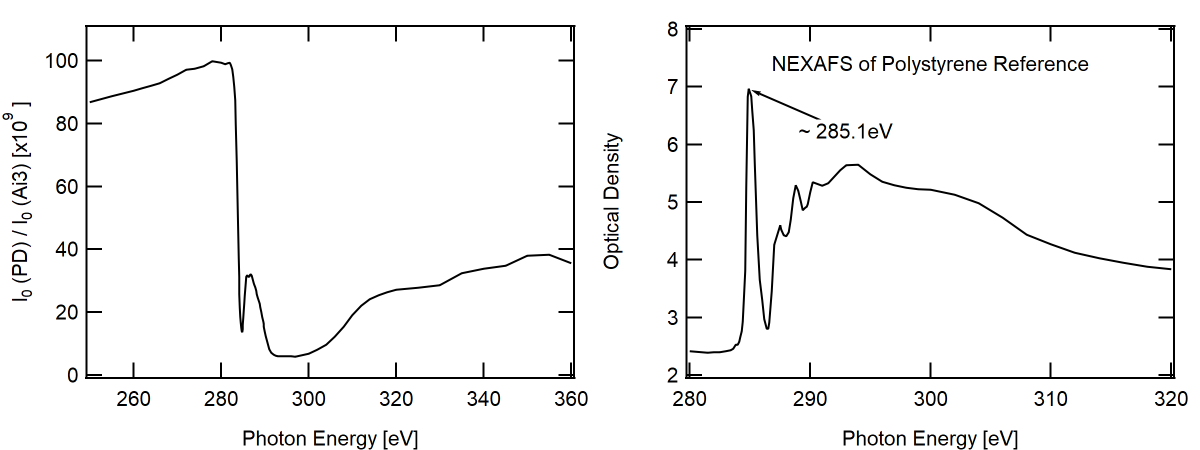
Left: Direct beam measured on the photodiode (PD) normalized to the upstream gold mesh mirror (Ai3). Right: Transmission NEXAFS on polystyrene sample. Energy of pi-pi antibonding resonance is indicated, (~285.1 eV)
- Once the CCD has reached -45 C, proceed with the following steps to characterize the direct beam.
Set the
Higher Order Suppressor = 12[deg]Set the
Horizontal Exit Slit = 150[mm]Set the
Beamline Energy = 270.0[eV]Set the
Exposure = 0.001[s]- Move the CCD to Beamstop Center Far
CCD X = 95.5[mm]CCD Y = 100[mm]CCD theta = 0[deg]
- Move the Beamstop to the edge of the camera.
Beamstop = 2[mm]
Set the
Sample Theta = 0[deg]- Move the sample plate below the beam
Either
Sample Z = -5orSample Z = 5[mm]
Warning
Imaging the direct beam on the CCD can damage the detector. Make sure the flux has been sufficiently suppressed before taking any images.
- Snap a picture to locate the direct beam.
Only continue if the CCD is not saturating
- Define an ROI around the beamspot
Open the
Menu name missingmenu from the top left corner of the CCD display imageAdjust the ROI dimensions until the beamspot is centered.
Standard ROI dimensions: 300 x 300 pixels with 2x2 binning (150 x 150 total pixels)
Set the cursors on the beamspot position to help with later alignment.
Note
If the sample is not level on the mounting plate the beam may drift left/right on the camera. The ROI dimensions can be extended to accomodate such drift. Updating them later will not require any new alignment.
Reducing the size of the ROI helps with detector readout time. A smaller ROI will speed up your measurements. Too small of an ROI may cause the beam to drift out of the FOV requiring you to repeat your measurements.
- Measure the intensity of the direct beam (with the CCD)
From the scans on the left of the panel, select
CCD Only No Motor MovementUpdate to save a single image
Warning
Be sure to reduce the dwell time in the motor scan options. The
Exposureused for the snap option is different and you will saturate/damage the detector.Record the Total Detector counts displayed on the RHS of the image.
Repeat the above steps with the direct beam blocked by the sample plate (dark image)
The difference in the two values is the total beam flux. This will be used later during sample alignment.
Calibrating piezo shutter deadtime
The piezo shutter has a short deadtime associated with each image on the order of 3ms. This means that each exposure will be approximately 3ms longer than you set in the software. It is important to take this offset into account when normalizing the detected reflectance to exposure. Fortunately, it is very easy to measure.
- Set the
Beamline Energy = 285.1[eV] This cuts the flux down so you can measure the intensity over several exposures.
- Set the
From the scan options, select
CCD Only No Motor Movement- Take images with increasing exposure time
Recommended series:
0.001, 0.002, 0.003, 0.004, 0.005, 0.01, 0.02[s]
- Plot the beam intensity (corrected for dark background) and extrapolate to 0 counts. The x-intercept will be the shutter offset.
See Reducing Data to 1D Profiles to learn fastest route to reduce data.
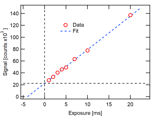
Total counts measured at 285.0 eV vs. exposure time. Linear extrapolation (dashed blue line) is used to determine shutter offset at 4 [ms]